Description
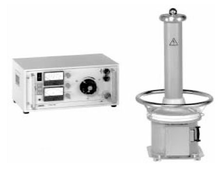
1.1 Design and Function:
The PGK HB instruments are designed as two-part High Voltage Testing Sets.
• Operating unit with all indicating/operating elements, with power supply and safety
  devices.
• High Voltage unit as oil-filled housing with High Voltage transformer with the choice of       a rectifier bar for half-wave rectification or a resistance bar as a damping resistor, With the PGK 70 - 2,5 HB, PGK 110 HB, PGK 150 HB and the PGK 260 the corona protection hood is used as oil expansion tank (conservator) and may not be removed or damaged. With the PGK 70 HB an air cushion in the housing (tube) works as a compressible volume for absorbing the oil expansion. That is why the H.V. unit may only be stored, shipped and operated vertically.
High Voltage generation
Generation of high voltage is carried out by a H.V. transformer supplied by an
variable transformer. During D.C. operation a half wave rectifier is connected after
the H.V. transformer. By turning the half-wave rectifier the polarity of the output
voltage can be changed. The capacity of the test object acts as smoothing
capacitor.
During A.C. operation, a damping resistor is connected to the H.V. circuit instead of the half-wave rectifier (with PGK 260 HB: option - not included)
The H.V. units of the PGK HB instruments are equipped with a potential grading
ring which can also be used as carrying ring. The instruments may be not operated
without this potential grading ring.
Operating ranges:
Depending on the load by the test object and the voltage set, the PGK HB
instruments are operating in one of the two operating ranges Continuous
Operation and Short-time Operation.
Continuous operation:
Within this operating range, from no-load to nominal rating up to cut off load the
instrument can be loaded continuously.
Short-time operation:
Within this operating range from cut off load to short circuit the instrument
switches current-limiting lamps into the primary circuit of the H.V. transformer in
order to reduce the thermal load of the instrument. Additionally, as a protection
against overload the over current protection switch (5) with its thermal and
magnetic tripping characteristic is tripped after a specific period terminating
operation. The time until tripping depends on load and takes from seconds (during
short-circuit) to hours (at maximum load).