Description
Secondary Injection Relay Test Equipment
Portable Test Equipment designed to test protective relays from the simplest overcurrent to the most sophisticated multifunctional digital protection.
The PTE range’s outstanding output power provides the best compromise between portability, ruggedness and application flexibility. The various secondary injection models that make up this range can be used both individually or interconnected to cover all the relay test applications required.
The PTE units provide powerful, yet easy to learn, intuitive on-board control for manual testing, as well as a connection to an external PC for fully automated testing and reporting.
The Mentor 12 integrates state-of-the-art fault simulation technology and a built-in computer with graphical touch screen to simplify the testing of the most sophisticated numerical protection with outstanding accuracy and efficiency.
Single phase current and voltage relay testing unit to 250 A.
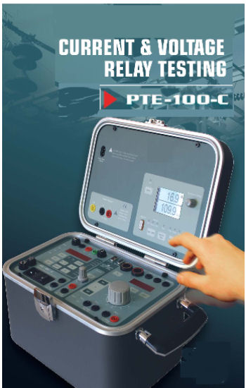
Model S-PTE-100-C
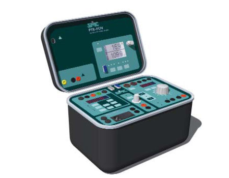
The S-PTE-100-C is a portable Universal test equipment for testing electromechanical, electronic, and digital relays. The equipment can output a variable current up to 250A, a variable AC Voltage up to 250V, a variable DC Voltage up to 350V. Also the unit incorporates a variable stabilized auxiliary DC Voltage supply up to 250V and a fixed AC Voltage output up to 110V, which can be variable with the PTE-FCF option.
The equipment is extremely compact and contains all the functions necessary for current and voltage relays. It incorporates various measurement functions such as a voltmeter, ammeter, frequency meter, as well as measures apparent power, impedance, and internal and external phase angles. From the front panel controls, the maximum output injection can be limited, used for example in testing instantaneous overcurrent relays. Injection time can also be limited, useful to safely test reclosing devices.
The PTE-100-C can communicate with a PC via the serial port RS-232, and can be connected to other PTE units via the BUS-PTE.
APPLICATIONS
– Testing of overcurrent and minimum/maximum voltage relays.
– Testing of overcurrent directional relays (option PTE-FCL).
– Testing of reclosing devices (option PTE-FCE).
– Testing of dc relays.
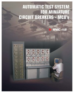
– Testing of MCB’s.
– Verification of the knee point in current transformers.
– Combined with the PTE-100-V, forms a complete single-phase system, capable to test differentials, synchronized, and inverse power relays, etc.
CHARACTERISTICS
– Variable current output up to 250 A.
– Variable AC voltage output up to 250V.
– Variable DC voltage output up to 350V.
– Variable auxiliary DC power supply to 250V.
– Auxiliary AC voltage output of 110V.
– Outputs are fully isolated and electronically protected.
– Timer resolution: 1 ms.
– Contains Voltmeter, ammeter, frequency meter, measures apparent power, impedance, and internal and external phase angles.
– Control of injection time.
– Control of the maximum value injected.
– Current can be pre-selected.
– 1,000VA for 1 minute.
– RS-232 Serial Port.
– PTE-BUS Port.
– Dimensions: 200 x 300 x 200 mm / 13.5 kg. 8 x 12 x 8 in / 30 lb.
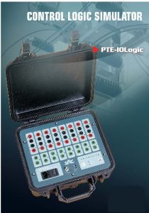
Control logic simulator
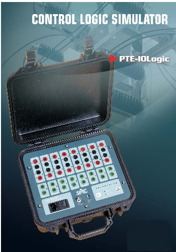
Model S-PTE-IO-LOGIC
The equipment S-PTE-IOLogic responds to the need to simulate and analyse, in the field or in electrical installations, a logical control sequences for substations, industrial control systems, remote control SCADA systems, and especially in the field of protection relays. Increasing so is this importance, as all the modern numeric relays incorporate control logic in the actual relay. The PTE-IO Logic monitors input signals and can condition the output response to these.
The main problem presented with these types of tests, is to check that the correct sequences of events are achieved during commissioning tests. This requires that the entire control systems and devices operate correctly with the actual mechanisms and elements of the installation. Not only does this need to be checked once, but usually repeated until the adequate adjustments are found and made, with the implied difficulty of this. This reduces the possibility of an incorrect operation may lead to damage in the installation. For these reasons, an equipment, such as the PTE- IO Logic represents an enormous advantage, in terms of safety and time saved.
The equipment is designed to operate in harsh environments, as the PTE-IO Logic is mounted in a hermetic anti-shock case. It’s reduced size and weights make it ideal for field use.
APPLICATIONS
– The application use of the of the PTE-IO Logic is extremely wide, given that it is capable of simulating any control situation, highlighting the following applications:
– Simulation and analysis of logic controls in protection relays.
– Simulation, analysis, and verification of the control system in substations.
– Simulation of any breaker system.
– Simulation and analysis of traffic control systems.
– Analysis of logical programs in automatic remote systems (SCADA)
– In general, to reproduce and to analyse any sequential programmed logic system.
– A system with these characteristics saves time and the possibility of damage in primary equipment especially during commissioning process. CHARACTERISTICS
– 16 Inputs in 8 groups galvanically isolated
– 8 isolated outputs
– Inputs and Outputs are configured with the software EURO-IO Log
– Dimensions: 150 x 340 x 300mm/5.4Kg. 6″ x 13″ x 12″/12 lbs.

